

Spiral Ultrafiltration Membrane
Product Overview
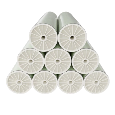
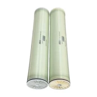
Spiral Wound Ultrafiltration Membrane Elements are precision-engineered pressure-driven membrane separation components designed to remove suspended solids, colloids, proteins, and high-molecular-weight macromolecules from aqueous streams. Operating via cross-flow filtration, feed solution flows parallel to the membrane surface while permeate passes through the asymmetric ultrafiltration skin layer and is collected via the central permeate tube.
These elements are deployed across industrial water treatment, wastewater polishing, and specialized concentration processes. Their performance and long-term durability depend on matching target substances, feed composition, required permeate quality, operating parameters, and chemical cleaning protocols.
For system designers, water treatment contractors, and industrial plant managers, key selection criteria include nominal molecular weight cut-off (MWCO), membrane polymer chemistry, active membrane area, feed spacer geometry, operating pressure limits, and chemical compatibility.



Product Categories
Latest Products


Working Principle and Construction
Separation Mechanism
Operating under hydraulic pressure gradients (typically 1.0 to 5.0 bar / 15 to 75 psi), the feed stream enters the element and travels through the feed spacer channels. Water and lower-molecular-weight solutes pass selectively through the UF membrane and permeate carrier, spiraling inward to the central collection tube. Retentate concentrates along the channel and discharges at the opposite end, minimizing surface cake layer buildup.
Element Construction and Materials
Membrane Sheet: Hydrophilic polyethersulfone (PES), polyvinylidene fluoride (PVDF), or modified polyacrylonitrile (PAN) cast on a stable non-woven polyester backing web for high chemical resistance and thermal stability.
Feed Spacer: Extruded diamond-net polypropylene (PP) mesh available in thicknesses from 28 mil to 80 mil to control hydrodynamic boundary layer thickness and solids passage.
Permeate Carrier: Knitted polyester tricot fabric optimized for low hydraulic resistance to permeate flow.
Outer Wrapping: Fiber-reinforced fiberglass outer shell with multi-component epoxy sealing, or sanitary full-fit hard-shell configuration with anti-telescoping devices (ATDs) on both ends to prevent structural distortion.
Adhesive System: Multi-component epoxy adhesive engineered to withstand continuous exposure to aggressive cleaning-in-place (CIP) chemicals and elevated operating temperatures.
Key Features
Optimized Hydrodynamics
Engineered feed spacer geometries (31 mil to 65 mil) induce controlled turbulence at lower cross-flow velocities, reducing concentration polarization and particulate accumulation in viscous streams.
High Chemical Resistance
Formulations tolerate continuous exposure to oxidizing agents, strong acids, and caustic solutions (pH 1.0 - 12.0), supporting rigorous clean-in-place (CIP) protocols.
Precision MWCO Cut-Off
Narrow pore size distribution ensures sharp separation boundaries between target macromolecules and permeate fractions.
Robust Mechanical Design
High-density fiberglass outer wrap and precision-molded anti-telescoping devices prevent structural telescoping under high feed pressure drops and transient hydraulic shocks.
Applications and Operating Conditions

Target Industries and Separation Tasks
Industrial Wastewater: Free and emulsified oil removal from metalworking fluids and refinery effluents.
Electrocoat Paint Recovery: Recovery of paint solids from rinse baths in automotive coating lines.
Food and Beverage: Clarification of fruit juices, concentration of gelatin, and fractionation of dairy proteins.
Reverse Osmosis Pretreatment: Reduction of silt density index (SDI) and turbidity in challenging surface water or secondary effluent feeds.
Standard Operating Limits
Maximum Operating Temperature: 50°C - 60°C (dependent on polymer chemistry)
Maximum Feed Pressure: 10.3 bar (150 psi) for standard elements; up to 20.6 bar (300 psi) for high-pressure configurations
Maximum Pressure Drop (Delta P): 1.0 bar (15 psi) per single element; 3.5 bar (50 psi) per multi-element vessel
PH Range (Continuous Operation): 2.0 - 11.0
PH Range (Short-term CIP): 1.0 - 12.0 at 50°C
Maximum Feed Chlorine Concentration: < 0.1 ppm (continuous); < 200 ppm (short-term sanitization)

Technical Specifications
|
Model Series |
Membrane Material |
Nominal MWCO |
Active Area (m2 / ft2) |
Feed Spacer Thickness (mil) |
Element Dimensions (Diameter x Length, inches) |
Clean Water Flux Range (LMH at 20°C, 1.0 bar) |
|
UF-8040-31 |
Modified PES |
50 kDa |
37.0 m2 / 398 ft2 |
31 |
7.9 x 40.0 |
80 - 120 |
|
UF-8040-46 |
Modified PES |
50 kDa |
30.0 m2 / 323 ft2 |
46 |
7.9 x 40.0 |
90 - 130 |
|
UF-8040-65 |
PVDF |
100 kDa |
22.0 m2 / 237 ft2 |
65 |
7.9 x 40.0 |
120 - 180 |
|
UF-4040-31 |
Modified PES |
50 kDa |
7.6 m2 / 82 ft2 |
31 |
3.9 x 40.0 |
80 - 120 |
|
UF-4040-46 |
PVDF |
100 kDa |
5.8 m2 / 62 ft2 |
46 |
3.9 x 40.0 |
120 - 180 |
Manufacturing and Quality Control
Elements are produced in a controlled-environment manufacturing facility utilizing automated membrane casting, precision sheet trimming, and multi-leaf rolling lines.
Incoming Material Verification
Lot-batch inspection of polymer resins, backing webs, and spacer nets for basis weight, thickness, and melt flow index.
Adhesive Curing Control
Epoxy potting and glue lines are cured in temperature-regulated ovens with monitored profile cycles to guarantee bond integrity under mechanical stress.
Integrity Testing
Every manufactured element undergoes individual vacuum decay or air-diffusion pressure testing prior to vacuum sealing and packaging to verify glue-line and permeate-tube seal integrity.
Performance Sampling
Standard batch testing includes clean-water permeability measurement and molecular weight cutoff verification via marker rejection testing.
Customization and Technical Support
Element Geometries
Standard 4040 and 8040 configurations, plus custom element lengths, specialized outer wrap materials, and customized permeate tube extension lengths for specific system housings.
01
Spacer Configurations
Tailored feed channel heights from 28 mil to 80 mil selected according to suspended solids load and viscosity of the feed stream.
02
Application Engineering
Pilot test data evaluation, membrane screening, flux projection modeling, and cleaning-in-place (CIP) chemical compatibility assessments.
03
Sample Testing
Evaluation membrane coupons available for bench-scale filtration trials and compatibility screening.
04
FAQ
With abundant experience, we are one of the most professional spiral ultrafiltration membrane manufacturers and suppliers in China. Welcome to wholesale high quality spiral ultrafiltration membrane in stock here and get pricelist from our factory. We also accept customized orders.
spiral ultrafiltration membrane, E Coat UF Membrane, E Coat UF Membrane 8240